Binary Ripple Counter Circuit Diagram
Ripple counter [solved] question 04: design a 4 bit binary ripple counter that trigger Counter bit ripple circuit electronics circuits simulator simulation
Draw and explain 3 bit asynchronous binary counter using positive edge
Ripple counter Counter bit ripple circuit simulator circuits simulation Counters circuitverse ripple flops truth 3bit counts
Counter ripple flip flop jk using binary circuit timing diagram diagrams
4-bit ripple counter4 bit binary counters mod 16 and it's working 8-bit ripple counter16. the 4 bit synchronous up counter circuit constructed with t.
Binary ripple counter in digital electronicsCounter ripple circuit timing flip bit jk flop diagram using table truth count flops along below diagrams so pulses given 1: a 4 bit ripple counter circuit. the output of one flip-flop clocksRipple counter.

Ripple counter
Counter flop binaryBinary counters working Counter bcd ripple circuitSolved consider the circuit for bcd ripple counter as shown.
Counter asynchronous flop jk triggered binary timing explain outputsCounter ripple binary digital electronics bit count Ripple modulo logic microcontroller circuitry khz figRipple flop hence asynchronous counters term rantle.

Counter counters ripple flops counts 2bit circuitverse
Ripple counter timing diagram binary circuit diagrams briefCounter bit ripple binary clock trigger question edge transcriptions count will Flip synchronous circuit flops constructedCounter bit binary digital flip circuit using flops.
Binary counter circuit diagram using ic 74hct4040Logic circuitry part 4 (pic microcontroller) 3 bit binary up counterCircuit counter binary diagram ic explanation working circuitdigest.

Draw and explain 3 bit asynchronous binary counter using positive edge
Counter ripple timing bit diagram circuit flip using flop jk binary diagrams briefRipple counter Circuit analysis.
.


Logic Circuitry Part 4 (PIC Microcontroller)

4-Bit Ripple Counter - Online Circuit Simulator

Ripple counter | Electronics Engineering Study Center

1: A 4 bit ripple counter circuit. The output of one flip-flop clocks
![[Solved] Question 04: Design a 4 bit binary ripple counter that trigger](https://i2.wp.com/www.coursehero.com/qa/attachment/13242246/)
[Solved] Question 04: Design a 4 bit binary ripple counter that trigger
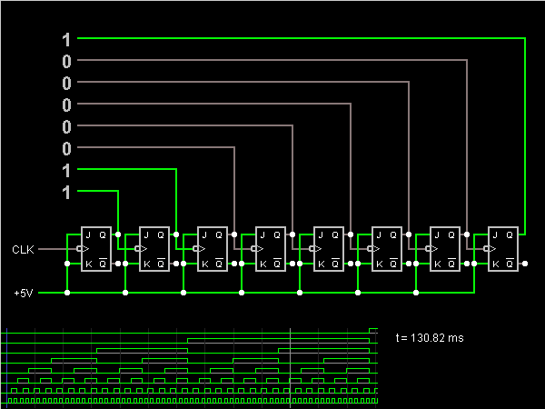
8-Bit Ripple Counter - Online Circuit Simulator

Counters | CircuitVerse

Draw and explain 3 bit asynchronous binary counter using positive edge