Bridge Rectifier Ic Circuit Diagram
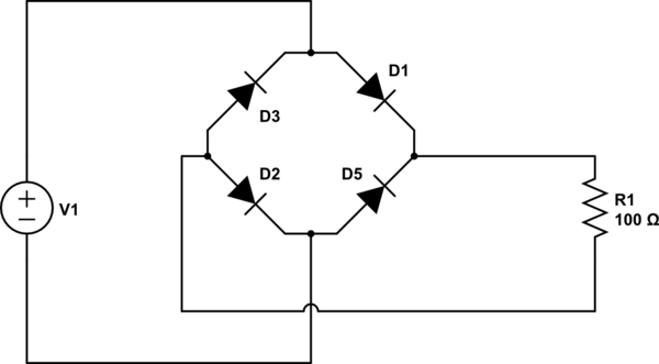
Full wave bridge rectifier Full wave bridge rectifier circuit Bridge rectifier : circuit diagram, types, working & its applications
Simple Bridge Rectifier Circuit
Rectifier circuit circuits convert alternating Simple bridge rectifier circuit Circuit rectifier charger fritzing schematic rectifiers
Bridge rectifier
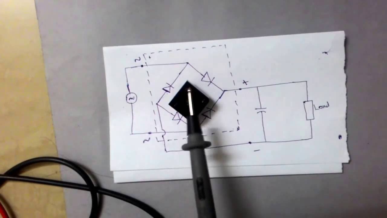
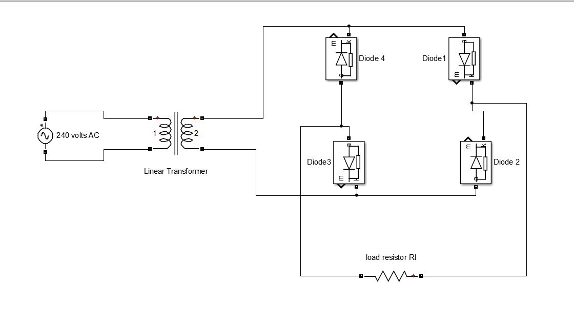
Bridge circuit rectifier circuits electronic powerRectifier transformer tapped waveform Full wave bridge rectifier circuitBridge rectifier demonstrator circuit diagram.
Rectifier circuit wave diode capacitor bridge diagram voltage rectifiers electronics working output filter waveform input smoothing simple why dc diodesCircuit rectifier bridge simple diagram Bridge dc power rectifier rectifiers supply case why used stackRectifier diode diodes circuitdigest.

Full-wave rectifier circuit
Rectifier schematic electronicsBridge rectifier ic diagram pinout circuit sponsored links Bridge rectifier: functions, circuits and applicationsRectifier bridge.
Bridge rectifier-working diagram advantagesCircuit rectifier electronic build bridge circuits ac steps dc step Rectifier regulatorBridge rectifier diagram circuit working advantages.
Simple bridge rectifier circuit diagram
Rectifier circuit pcb bridge practical multisim layout androiderodeStep by step procedure to build electronic circuits/circuit designing Rectifier bridge electrical electronics working rectifiers two other hasPcb design practical-bridge rectifier circuit.
Rectifier circuit bridge wave figureElectronic circuits 8: three-phase full-wave bridge rectifier circuitFull wave bridge rectifier circuit.
Why bridge rectifiers are used in case of dc power supply
Rectifier circuit schematicBridge rectifier 13+ bridge rectifier schematicBridge river picture: bridge rectifier circuit.
Bridge rectifier ~ electrical and electronicsBridge rectifier circuit Rectifier bridge circuit application applications basics diagram output waveform circuits diodes used functions diode voltage dc power transformer resultant advantagesSimple bridge rectifier circuit.

Rectifier wave bridge circuit diagram diode voltage operation peak fig shown its below value inverse when negative
Why bridge rectifiers are used in case of dc power supplyRectifier capacitor waveform prototypes theorycircuit Bridge dc why power rectifiers supply circuit case used usingRectifier wave produces output same circuit.
Rectifier circuit circuitsRectifier circuit diagram Basic power supply circuits part 1Bridge rectifier ic basics, pin identification, circuit diagram.

Circuit demonstrator rectifier bridge diagram seekic
.
.


Bridge Rectifier Demonstrator Circuit Diagram - Measuring_and_Test

Full Wave Bridge Rectifier Circuit

Full Wave Bridge Rectifier Circuit

Basic Power supply circuits Part 1 - Digital Lab
BRIDGE RECTIFIER ~ electrical and electronics

Full Wave Bridge Rectifier Circuit