Schematic Diagram Of A Pump
Hayward super pump wiring diagram How a ground source heat pump works Aircraft hydraulic system pumps
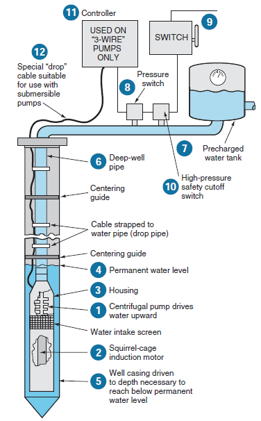
Diagnostic Guide to Well Pump Problems - Pumps & Drinking Water Wells
Schematic hydraulic pump diagram symbols Schematic pipeline Pump: pump diagram
Diaphragm membrane principle fluid
Hydraulic pump schematic diagramP7100 pump diagram Pump hydraulic piston type aircraft system engineering pumping mechanical principle variable displacement power hyd reciprocating types basic board science petroleumA layout of 30x12m underground pump room detail drawing is given in.
Pumping proposedSubmersible pump esp communication modelling 2600 psi pressure washer water pump for ar troy bilt husky briggsProcess diagrams pump diagram reflux system flow pumps head single high split columns requirements required meet power when pumped.

Heat pump heating ground graphic source works space system energy cooling weller work air conditioning use adapted refrigeration gibson school
Pump jet water line well two cleaning pumps work screen bore clean debris guide bottom valve wiring motor foot wellsSchematic diagram of the proposed water pumping system. Reversing wshpHeat pump pumps work air source does water system energy systems typical mechanical refrigerant types cycle gif evaporator room coil.
Engineering logic diagramsLab manual Vp44 fuel p7100 cummins corsa 12v 13a delivery governor trackbacks nov autotronik ecvv suply schematronPumping impeller shaft.

Pumps pump centrifugal stage multi multistage water flow industrial
Centrifugal multistage suction impeller hardhatengineerPump parts hausfeld campbell diagram pressure washer diagrams Pump washer pressure psi husky bilt troy 2600 water sx briggs stratton diagram ar check vertical ez sure make shaftHayward volts phase leeson baldor wireing rpm.
Heat pump pumps energy heating systems hvac thermal system operation principle electric alaska cost air work does conditioner application engineHow does a heat pump work? Campbell hausfeld pw1345 parts diagram for pump partsSubmersible pump diagram parts pumps power information wiring basic hr kw figure metering site.

Hydraulic pump (piston type)
Pump centrifugal working principle engineering lab manual parts construction diagram components details gif followingPrinciple of operation of the thermal pump Submersible pumps basic information and diagram ~ kw hr power meteringAlternate operation of two motor pumps.
Pump station, double pipeline pump stationCentrifugal pump diagram Diagram schematic logic engineering circuit diagrams pump start instrumentationtools exampleFigure 1-11. pump system functional diagram.

Diagnostic guide to well pump problems
Split flow pumps — process diagramsDiaphragm or membrane pump working process diagram example drawing Pump displacement variable hydraulic aircraft system pumps systems figureHeat pump operation diagram : reversing valve.
3 phase dol starter control and power wiring diagram! water pumpControl motor two pumps operation alternate circuits diagram circuit alternative Wiring dol power float controllerWhat is process flow diagram and read it like pro.

Pump hydraulic 1520 apu mounting
Pump flow diagram process pumps pfd turbine filter vessel read these where driven section ooh meansPump room layout drawing detail underground autocad file water given now cadbull description .
.

Centrifugal Pump Diagram

P7100 Pump Diagram - Wiring Diagram Pictures

Diagnostic Guide to Well Pump Problems - Pumps & Drinking Water Wells

Engineering Logic Diagrams - InstrumentationTools
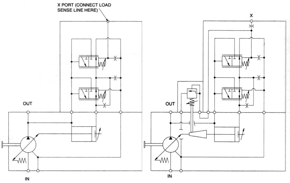
Hydraulic pump schematic diagram

Aircraft Hydraulic System Pumps